
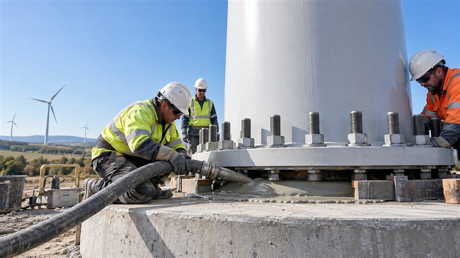
Wind turbine grout forms a small but critical part of the structural load path between a tower or support structure and its foundation. It must fill the designed space, develop strength within the erection schedule, maintain bearing contact and resist millions of stress cycles without unacceptable cracking or deformation. This guide focuses on high-strength cementitious grout for onshore tower-base applications while explaining why offshore grouted connections require a separate, project-specific engineering approach.
Where Wind Turbine Grout Is Used
Onshore towers commonly transfer load through a circular steel flange connected to an anchor cage embedded in a reinforced-concrete foundation. Grout fills the gap between the flange and prepared concrete, providing continuous bearing and transferring compressive and shear forces while the anchors resist uplift and overturning effects.
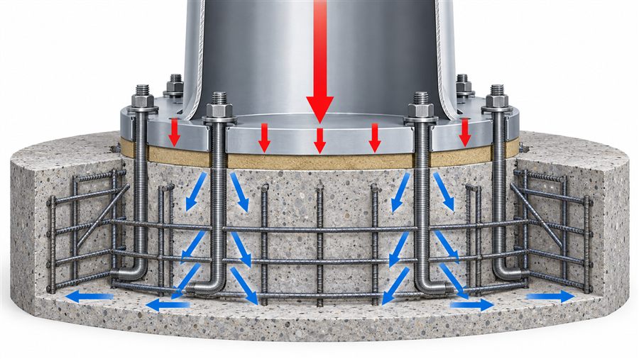
Offshore “grouted connection” is a broader term. Grout may fill the annulus between a monopile and transition piece, or between a jacket leg and pile. Those geometries experience confinement, shear keys, marine exposure, installation movement and fatigue conditions that differ from an onshore flange. A product qualified for an onshore base plate should not be assumed suitable offshore without design approval and the required qualification.
Why Compressive Strength Alone Is Not Enough
High compressive strength is necessary, but a wind turbine foundation is a cyclic structural system. Product selection should consider the following properties together.
| Property | Why it matters | How to specify responsibly |
|---|---|---|
| Early compressive strength | Controls when erection or bolt-tensioning steps may proceed | State required strength at actual curing temperature and test age |
| Characteristic/design strength | Supports structural verification | Use the design standard’s specimen geometry, statistics and safety factors |
| Elastic modulus | Influences deformation and load distribution | Use tested modulus compatible with the structural model |
| Fatigue resistance | Repeated wind-induced cycles can govern service life | Require testing/assessment under the applicable design framework |
| Volume stability | Loss of contact reduces effective bearing area | Require applicable expansion/shrinkage tests and curing controls |
| Creep | Long-term deformation may alter contact and bolt forces | Obtain project-relevant data where design requires it |
| Flow retention | Enables complete placement over the pumping duration | Verify at expected temperature, hose length and batch rate |
| Segregation and bleeding | Voids and weak zones interrupt the load path | Set visual and test limits; conduct a full-scale trial when risk warrants |
| Thermal behavior | Thick placements can heat internally and create gradients | Model or measure temperature for large volumes and extreme weather |
ASTM C1107/C1107M-20 covers packaged dry hydraulic-cement grout intended for use under applied load where height below the initial placement height is to be avoided. It is useful for qualifying nonshrink grout, but compliance does not by itself demonstrate fatigue suitability for a particular turbine.
DNV-ST-0126 provides general principles and requirements for wind turbine support structures. DNV-ST-C502 addresses offshore concrete structures and is also referenced in wind-industry fatigue assessment. The engineer must identify the governing contract editions and connection-specific criteria.
Data Example: Read Product Claims in Context
Published technical data help establish a screening range, but they must not be generalized to all grouts. Two current manufacturer examples illustrate this point:
- SikaGrout-4316 states compliance with ASTM C1107 at recommended consistencies, up to 4,300 psi (29.6 MPa) compressive strength at 8 hours, 95% effective bearing area, placement from 2 to 38°C, and an ultimate compressive-strength claim of 16,000 psi (110 MPa). Its page also reports DNV fatigue testing for wind-turbine applications.
- MasterFlux 1300 is described for onshore anchor-cage foundations, with a 0–40°C application range, 25–600 mm application thickness, at least 60 MPa after one day and a strength class of at least C100/115 under EN 206 terminology.
These values come from different products, test systems and regional documents; they are not directly interchangeable design values. Confirm water content, consistency, specimen size, curing, temperature and statistical basis before comparison. Use the project engineer’s approved submittal—not a marketing table—as the acceptance document.
How to Specify Wind Turbine Foundation Grout
1. Start with the connection design
Provide the grout supplier with the flange geometry, nominal and tolerance-adjusted gap, radial flow distance, anchor arrangement, vent and formwork details, total volume, design loads and planned construction sequence. Specify whether the grout will be poured, pumped or continuously mixed from bulk bags.
The design team should define:
- Required strengths at release, erection and design ages
- Characteristic strength and modulus used in calculations
- Fatigue qualification and stress range
- Minimum and maximum placement temperature
- Maximum lift thickness and thermal-control limits
- Required flow, flow-retention time and allowable bleed/segregation
- Volume-change, creep, durability and exposure requirements
- Test methods, specimen geometry, curing and acceptance frequency
Avoid a specification that only says “100 MPa nonshrink grout.” It leaves unanswered when the strength is needed, how it is measured, and whether the material can be installed without voids.
2. Confirm geometric and thermal limits
Grout thickness affects heat generation, aggregate settlement risk and placement pressure. The manufacturer must approve the actual minimum and maximum gap. For a large annular base, the center can become much warmer than the exposed surface, especially in warm weather. A thermal plan may require temperature-conditioned water, shaded material, monitored peak temperature, insulation or staged removal of protection.
3. Approve the complete method statement
The method statement should connect product data to site execution: storage, mixer type, water measurement, batch size, mixing time, pump capacity, hose diameter, standby equipment, formwork pressure, placement direction, venting, finishing, curing and contingency actions. A technically suitable grout can still fail through an incomplete method.
Estimating Grout Quantity
For a simple horizontal annular layer with outer diameter Do, inner diameter Di and thickness t, theoretical volume is:
V = π ÷ 4 × (Do² − Di²) × t
Example: Do = 5.00 m, Di = 4.20 m, and t = 0.08 m.
V = π ÷ 4 × (5.00² − 4.20²) × 0.08 = 0.462 m³
If the approved allowance for formwork, hose, surface irregularity and waste is 10%:
Order volume = 0.462 × 1.10 = 0.508 m³
Convert volume to bags using the tested product yield at the approved water content, not bag mass alone. The example is geometry only; actual foundations may include shear keys, bolt pockets, uneven substrates or different boundaries. Survey dimensions before ordering and define backup stock in the placement plan.
Preparation Before Mixing
Concrete substrate
Remove laitance, curing compound, oil, loose material and other bond breakers. Mechanical preparation should expose sound, clean aggregate without damaging the foundation. Bring the substrate to the moisture condition required by the manufacturer—often saturated surface-dry for cementitious grout—so dry concrete does not remove water from the fresh grout and standing water does not dilute it.
Steel and anchors
Clean contact surfaces to the project requirement. Verify flange level, gap, anchor position, torqueing sequence and any sleeves or bond-breaking zones against the approved drawing. Protect threads from grout contamination where necessary.
Formwork
Forms must be watertight, rigid and designed for the hydrostatic pressure of fluid grout. Provide a continuous head or pumping arrangement, controlled outlets and vents at high points. Leakage is not only a housekeeping issue: it can lower head pressure and interrupt the flow front.
Mixing and Pumping Procedure
Use the exact potable-water quantity approved in trials and measure it by mass or with a verified meter. Do not estimate with uncalibrated buckets. Condition the dry material and water so the mixed-grout temperature stays within the approved range.
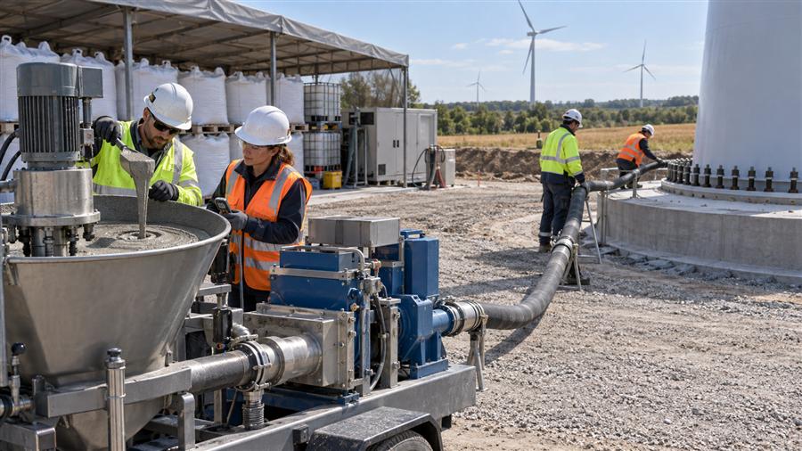
A typical controlled sequence is:
- Pre-inspect mixer, pump, hoses, generator, water supply, forms and backup equipment.
- Add the specified water and dry grout in the manufacturer’s sequence.
- Mix with the approved high-shear or colloidal equipment for the stated time.
- Check the first batch for flow, temperature, density or other project criteria.
- Pump continuously from one planned location so one coherent flow front displaces air toward vents.
- Maintain sufficient head and avoid trapping air by feeding from opposing sides without an engineered plan.
- Continue until sound grout reaches outlets and the required final level is established.
- Protect immediately using the approved curing and temperature-control method.
Never add extra water to recover lost flow. More water can reduce strength and modulus, increase separation and change dimensional stability. If flow falls outside the approved window, stop and follow the written rejection or contingency procedure.
Field Quality Control and Traceability
Quality control must represent the placed grout. Record product name and lot, bag count or silo mass, water per batch, batch times, grout and ambient temperature, flow results, placement start/finish, pump interruptions and specimen identification.
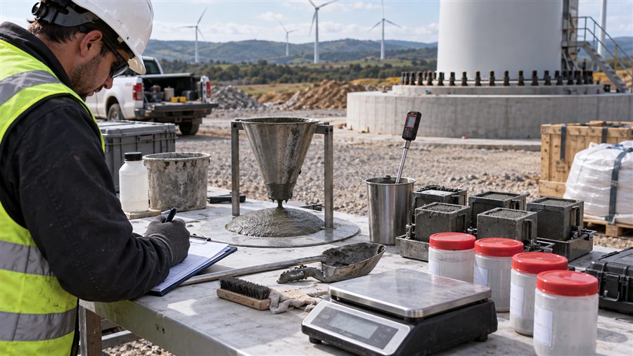
The inspection and test plan may include:
- Incoming package condition and shelf life
- Water calibration and grout yield
- Initial and time-dependent flow using the specified method
- Fresh density, temperature, segregation and bleeding observations
- Compressive-strength specimens at defined early and later ages
- Temperature monitoring within the placement and at the surface
- Visual inspection after form removal, including cracks, voids or leakage paths
- Non-destructive or intrusive verification if the acceptance plan requires it
Test-method consistency is essential. A 50 mm cube, 75 mm cube and cylinder can produce different values; field-cured and laboratory-cured specimens can also diverge. Do not compare numbers unless geometry, preparation, curing, capping and loading method are aligned.
Frequent Failure Modes and Preventive Controls
| Failure mode | Possible cause | Preventive control |
|---|---|---|
| Voids beneath flange | Low head, premature loss of flow, poor venting, leakage | Full-scale flow trial; watertight forms; one-direction placement and vents |
| Low early strength | Excess water, low grout temperature, poor mixing or curing | Calibrated water; temperature plan; verified mixer and protected curing |
| Cracking | Thermal gradient, restraint, rapid drying, excessive thickness or movement | Thermal assessment; correct curing; approved thickness; movement control |
| Segregation | Too much water, unsuitable equipment or excessive retempering | Fixed water ratio; trial the actual mixer and pump; reject nonconforming batches |
| Cold joint | Pump interruption or insufficient production rate | Capacity calculation, backup pump/power and sufficient labor/material |
| Loss of bearing | Shrinkage, voids, weak surface or long-term deformation | Volume-stability tests, substrate preparation and design-relevant material data |
| Early-age offshore damage | Relative movement during curing | Connection-specific movement analysis and installation controls |
DNV describes early-age cycling as relative displacement caused by wave and current loading while offshore grout cures. DNV-ST-0126 currently uses a 1 mm limit for relative movement during the initial curing phase, while an industry project is investigating the evidence needed for future guidance. This offshore criterion should not be copied blindly into an onshore method statement.
Procurement and Prequalification Checklist
Before approving a wind turbine grout supplier, request:
- Current technical and safety data sheets for the exact manufacturing location and product.
- Third-party or accredited test evidence for the specified standard and properties.
- Strength-versus-temperature data at the project’s release ages.
- Elastic modulus, fatigue, creep and volume-stability data required by the designer.
- Flow retention and pumpability evidence for the intended geometry and equipment.
- Yield, packaging options, lot traceability, shelf life and storage limits.
- A project-specific installation recommendation and technical support plan.
- References only where they can be verified; never substitute an unrelated project claim for testing.
Evaluate total installed risk as well as price per tonne. Yield variation, slow production, rejected batches or an interrupted pour can cost far more than the grout itself.
Frequently Asked Questions
What strength should wind turbine grout have?
There is no single universal value. The designer must state the characteristic/design strength and the early strength needed for each construction step, including test method, specimen type, curing and temperature. Published products may exceed 100 MPa at later ages, but that does not establish the correct project value.
Is ASTM C1107 compliance sufficient for a wind turbine foundation?
No. ASTM C1107 addresses packaged nonshrink hydraulic-cement grout performance. A turbine application may additionally require high early strength, elastic modulus, fatigue, creep, thermal and pumpability evidence tied to the structural design.
Can ordinary nonshrink grout be used under a turbine tower?
Only if the engineer verifies that it meets every design and installation requirement. Many general-purpose grouts lack the documented fatigue performance, modulus, thick-section capability or pumping window required for large turbine bases.
Why must grout be placed continuously?
Continuous placement helps maintain one advancing flow front and reduces the risk of trapped air and cold joints. The batch plant, mixer, pump, hose route and backup equipment should be sized from the required volume and allowable working time.
When can the tower be released for the next construction step?
Only after the specified in-place curing condition and acceptance strength are achieved, and after approval under the project procedure. Elapsed time alone is not evidence of strength, especially in cold weather.
Conclusion
Reliable wind turbine grout performance comes from matching material data to the connection design and then protecting that design intent during placement. Define fatigue, modulus, flow, thermal and early-strength requirements; validate the actual equipment and weather window; and record every batch. QD Material can help review grout requirements and plan trials, while final approval remains with the project’s engineer and quality system.
Technical References
- ASTM C1107/C1107M-20, Standard Specification for Packaged Dry, Hydraulic-Cement Grout (Nonshrink).
- DNV-ST-0126, Support Structures for Wind Turbines, Edition 2021-12.
- DNV-ST-C502, Offshore Concrete Structures.
- DNV: Early Age Cycling of Grouted Connections.
- SikaGrout-4316 technical product page.
- MasterFlux 1300 technical product page.
Technical note: This article supports preliminary selection and content marketing; it is not a structural design or installation specification. Confirm product data, standard editions and project requirements with the engineer of record and grout manufacturer.