

Non-shrink grout is engineered to fill confined gaps and create reliable contact between structural components. Yet “non-shrink” does not make an installation failure-proof. A grout with excellent laboratory data can still develop voids, cracks, low strength or poor bond when product selection and field controls do not match the application.
The most useful response is not to blame the material or cover the visible symptom. It is to identify where the load path, material properties or installation process departed from the approved design. This guide explains eight common causes of non-shrink grout failure, how to recognize them and how suitable QD grout models can help prevent recurrence.
Quick answer: Most grout problems trace back to one or more of five controls: correct product, measured water, sound substrate, continuous placement and suitable curing. QD-60 is designed for equipment foundations, base plates, anchors and secondary grouting. QD-85 and QD-100 are dedicated high-strength grouts for precast rebar sleeve connections.
What Does Non-Shrink Grout Failure Look Like?
Grout failure is not limited to complete crushing. Early warning signs may include:
- Hollow-sounding or unsupported areas beneath a base plate
- Cracks along exposed grout shoulders
- Separation between grout and the concrete substrate
- Bleeding, settlement or visible segregation during placement
- Compressive-strength results below the specified requirement
- Movement, vibration or loss of equipment alignment
- Leakage from formwork followed by incomplete filling
- No grout, intermittent grout or contaminated grout at a sleeve outlet
- Rust staining, moisture entry or deterioration under aggressive exposure
These symptoms do not prove a single cause. Investigators should review drawings, batch records, water, temperatures, flow results, curing, test specimens and the surrounding concrete.
Cause 1: Selecting Grout by Strength Alone
A common error is to compare only 28-day compressive strength. Strength does not confirm that grout can fill the gap, remain stable, bond or tolerate the service environment.
Selection should also consider:
- Minimum and maximum placement thickness
- Flow distance and access
- Fluid, flowable or plastic consistency
- Required strength at the planned loading time
- Working time at the expected site temperature
- Plastic and hardened volume stability
- Vibration, water, chemicals and service temperature
- Pumping method and hose arrangement
- Applicable project standard and test method
Prevention
Define the application first. Use an equipment foundation grout for a formed base-plate gap and a dedicated sleeve grout for a confined precast connection. If the exposure includes severe chemicals, heavy dynamic loading or unusual temperatures, obtain an application-specific recommendation instead of assuming a general cementitious grout is suitable.
Cause 2: Adding Too Much Water
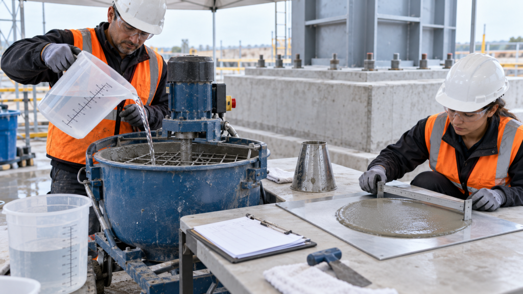
Extra water is one of the fastest ways to create apparent flow and long-term trouble. It can lower strength, increase bleeding, encourage segregation and alter dimensional performance. Retempering grout that has begun to stiffen is equally risky because it changes a batch after hydration is underway.
Prevention
Measure clean water for every full bag with a calibrated container. Keep the quantity within the current Technical Data Sheet range, record it on the batch log and verify flow using the specified method. If grout is too stiff, review material temperature, mixing time, equipment, elapsed time and product choice. Do not solve a placement problem by exceeding the water limit.
Cause 3: Poor Mixing or Inconsistent Batches
Short mixing may leave dry pockets and poorly dispersed additives. Excessive speed can entrain air. Uncontrolled partial bags make the powder-to-water ratio difficult to repeat. Long delays between batches can interrupt placement and create a cold joint beneath the plate.
Prevention
Use a suitable mixer, follow the required addition sequence and mix whole bags for the stated time. Size labor and equipment for continuous supply. Trial larger placements to confirm output and pump compatibility.
Cause 4: Weak, Dirty or Incorrectly Conditioned Concrete
Grout cannot develop reliable bond to laitance, dust, curing compound, oil or unsound concrete. A dry cementitious substrate may absorb water from fresh grout at the interface. Standing water creates the opposite problem by locally diluting the mix.
Prevention
Remove weak concrete and contaminants, expose sound material as required by the specification, and clean the base plate underside. For cementitious grout, bring the concrete to saturated-surface-dry condition unless the product instructions state otherwise. SSD concrete is damp internally but has no puddles on the surface.
Cause 5: Trapped Air or Interrupted Placement
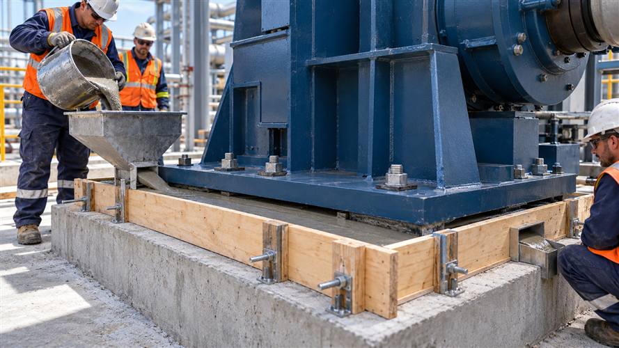
Pouring under a base plate from several directions may surround and trap an air pocket. Low head, narrow access, leaking forms or a pause between batches can also prevent full contact. The grout may look complete around the perimeter while a hidden central void remains.
Prevention
Build rigid, leak-tight forms with a raised headbox on the placing side and a clear outlet on the opposite side. Place continuously from one side so the advancing grout front pushes air toward the outlet. Maintain enough head to sustain flow without creating turbulence. Do not use a concrete vibrator unless the grout manufacturer specifically permits it.
Cause 6: Temperature and Working-Time Mismanagement
Heat can shorten working time and accelerate moisture loss; cold can delay strength development. Sun, wind, frost and long pump routes increase the risk.
Prevention
Record material and site temperatures. Stay within current data-sheet limits, shorten the route when necessary and protect the placement from weather. Approve loading by verified strength, not elapsed time.
Cause 7: Inadequate Curing or Poor Shoulder Detailing
Exposed grout edges lose moisture faster than material confined beneath a plate. Wide, unsupported shoulders are particularly vulnerable to drying and thermal cracking. Premature form removal or early vibration can also damage young grout.
Prevention
Start the specified curing procedure as soon as finishing permits. Protect exposed surfaces with the approved wet-curing system or compatible curing method. Keep shoulders within the project detail and avoid unnecessary projections. Do not treat every surface crack as cosmetic; determine whether it extends into the load-bearing zone.
Cause 8: Incomplete Precast Sleeve Filling
Sleeve grouting has a different failure mechanism from open base-plate grouting. The internal cavity cannot be inspected directly, and narrow passages can be blocked by debris, displaced seals or stiff grout. Stopping before stable grout reaches the outlet may leave air around the reinforcing bar.

Prevention
Inspect and clean the sleeves before erection, confirm seals and port access, then inject through the specified lower inlet. Continue until cohesive, uncontaminated grout emerges steadily from the designated outlet. Seal the ports in the approved sequence and maintain a connection record for each sleeve or panel.
Choosing QD-60 for Base Plates and Equipment Foundations
QD-60 is a high-performance, polymer-modified cementitious grout developed for equipment foundations, anchor bolts, secondary grouting and related structural applications. Its selection focus is self-leveling flow, early strength, controlled micro-expansion and stable bearing beneath installed components.
The supplied QD technical reference lists the following performance indicators:
| QD-60 property | Published model value |
|---|---|
| Initial flow | ≥290 mm |
| 1-day compressive strength | ≥20 MPa |
| 28-day compressive strength | ≥60 MPa |
These figures are useful for initial selection, but they do not replace the current data sheet. Confirm the water range, test method, temperature, working time, lift thickness and loading requirement for the exact supply and destination market.
QD-60 can help prevent problems associated with poor flow or unstable bearing when it is correctly specified. It cannot compensate for oil-contaminated concrete, open form joints, excessive water or interrupted placement.
Choosing QD-85 or QD-100 for Rebar Sleeve Connections
QD-85 and QD-100 are flowable, micro-expansive sleeve grouts for connecting reinforcement in precast construction. They are designed for strong bond to the rebar and sleeve while providing the flow needed for confined injection.
| Model | Primary application | Initial flow | 28-day compressive strength |
|---|---|---|---|
| QD-85 | High-strength precast rebar sleeve connections | ≥300 mm | ≥85 MPa |
| QD-100 | Higher-strength precast rebar sleeve connections | ≥300 mm | ≥100 MPa |
The supplied technical reference identifies a 30-minute use window for mixed grout. Treat this as a product-reference value and confirm it against current documents and actual project temperature. The structural designer or approved sleeve system should determine whether QD-85 or QD-100 is required; choosing the higher grade without design review does not correct a poor installation method.
Symptom-to-Cause Troubleshooting Table
| Observed symptom | Likely causes to investigate | Immediate response |
|---|---|---|
| Voids beneath a plate | Multi-direction placement, low head, leakage, stiff mix, interrupted supply | Hold loading, map the void and obtain an engineered repair decision |
| Low strength result | Excess water, wrong specimen method, cold curing, sampling error, incorrect product | Quarantine the affected work and review batch and laboratory records |
| Bleeding or segregation | Excess water, unsuitable mixing, unapproved vibration | Stop placement and do not rework the batch by adding powder on site |
| Cracked grout shoulder | Rapid drying, wide projection, thermal effects, movement | Assess crack depth and whether the bearing zone is affected |
| Debonding | Laitance, oil, dust, dry substrate, standing water | Determine the extent and remove unsound material under an approved repair plan |
| No grout at sleeve outlet | Blockage, leakage, insufficient flow, premature stop | Keep the connection out of service and follow the sleeve system’s nonconformance procedure |
| Equipment vibration | Incomplete bearing, alignment error, loose anchors, unsuitable grout | Stop or limit operation as required and conduct a combined mechanical/structural review |
Do not patch or load defective work without an approved investigation. A surface repair may hide the original load-transfer problem.
Pre-Pour Checklist for Preventing Grout Failure
Before mixing begins, verify that:
- The approved grout model matches the application and service environment.
- Current technical documents and the method statement are available on site.
- Bags are dry, intact, within shelf life and from recorded lots.
- The substrate is sound, clean and in the required moisture condition.
- Base-plate alignment, clearances, anchors and access have been checked.
- Forms are rigid, sealed and arranged for one-direction flow.
- Sleeve inlets, outlets, seals and connection IDs have been inspected.
- Water containers, mixers, pumps and flow-test equipment are ready.
- Batch size and crew capacity support continuous placement.
- Temperatures and weather protection are within the approved limits.
- Test specimens, batch logs and photo records are planned.
- Curing materials are beside the work area before placement starts.
Frequently Asked Questions
Can non-shrink grout still crack?
Yes. “Non-shrink” refers to defined volume-change performance under test conditions. Rapid drying, poor shoulder geometry, excessive water, restraint, movement or thermal effects can still cause field cracking.
Why are there voids beneath a base plate?
Common causes include pouring from opposing sides, insufficient grout head, an interrupted pour, leaking forms, low flow or trapped debris. Continuous one-side placement helps move air toward the outlet.
Can more water fix low grout flow?
No. Use only the permitted water range. Correct the temperature, mixing process, equipment, hose arrangement, placement delay or product selection instead.
When should QD-60 be used?
QD-60 is intended for equipment foundations, machinery and structural base plates, anchor bolts, prepared cavities and secondary grouting where stable bearing and flow are required.
When should QD-85 or QD-100 be used?
Use them for engineered precast rebar sleeve connections. The connection design, required strength grade, sleeve system and applicable standard should determine which model is approved.
Can defective grout simply be patched?
Only after the defect has been investigated. A patch may repair an exposed edge but will not restore hidden bearing or an incompletely filled sleeve. The engineer should approve the repair scope and acceptance method.
Conclusion
Non-shrink grout failure is usually a system problem, not a single material property. Correct selection must be followed by controlled water, suitable mixing, sound substrate preparation, continuous placement, temperature management, curing and traceable quality records.
For equipment foundations and base plates, QD-60 provides a targeted non-shrink grouting solution. For precast rebar sleeve connections, QD-85 and QD-100 provide higher-strength, pumpable options. Send Qiandao New Materials the drawings, gap or sleeve details, required strength ages, site temperatures, placement method and applicable standard for a project-specific review.
Technical note: This article provides general guidance only. Project drawings, the engineer’s specification, equipment or sleeve-system requirements, approved repair procedures and the current Technical Data Sheet take precedence.
Suggested Internal Links
- QD-60 product page:
https://qdmaterials.com/product/qd60-grouting-material-for-precast-rebar-connection/ - Product range:
https://qdmaterials.com/products/ - Contact page:
https://qdmaterials.com/contact/ - Related article: How Non-Shrink Grout Solves Modern Construction Problems
- Related article: Non-Shrink Grout Installation Precautions
- Related article: Hot-Weather Non-Shrink Grouting Guide
- Related article: Cold-Weather Non-Shrink Grouting Guide
References
Qiandao New Materials, supplied QD grout technical reference for QD-60, QD-85 and QD-100 model data.
ASTM International, ASTM C1107/C1107M-20: Packaged Dry, Hydraulic-Cement Grout (Nonshrink).
American Concrete Institute, ACI SPEC-351.4-24: Cementitious Grout Installation between Foundations and Equipment Bases.
American Concrete Institute, ACI PRC-351.1-12: Report on Grouting between Foundations and Bases, reapproved 2024.
Sika, Cementitious Grouting of Machine Bases and Base Plates.