
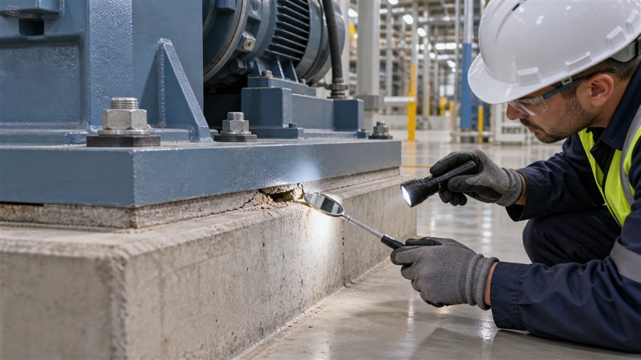
A visible crack does not by itself prove structural non-shrink grout failure, and an intact grout shoulder does not prove full bearing beneath a baseplate. Reliable diagnosis connects observations to the equipment’s load path, movement history and installation records. This guide explains how to assess cracks, voids, debonding and weak grout without guessing—and how to choose between monitoring, localized repair and replacement under engineering control.
What Counts as Grout Failure?
The grout beneath a machinery or structural base transfers load from an irregular steel surface into a concrete foundation. Depending on the design, it may maintain alignment, share load with shims, protect shims, or provide continuous bearing. Failure therefore means that the grout no longer performs its assigned function, not merely that its exposed edge looks imperfect.
Examples of functional failure include:
- Loss of required bearing area beneath the plate
- Crushing or progressive cracking under service load
- Debonding accompanied by movement or alignment change
- Inadequate strength at the required release age
- Excessive volume change that opens a load-transfer gap
- Chemical or thermal deterioration incompatible with service
- A cold joint or void that interrupts the designed load path
Cosmetic crazing, a chipped edge or a crack confined to an oversized shoulder may be less serious. It still needs documentation because moisture ingress or continued movement can worsen the condition.
“Non-Shrink” Does Not Mean Zero Field Movement
ASTM C1107/C1107M-20 covers packaged dry hydraulic-cement grout intended for use under applied load where a decrease below the initial placement height is to be avoided. Its performance is determined under prescribed laboratory conditions.
Two related methods clarify the limits of the term:
- ASTM C827/C827M-23 measures comparative height change from placement until the material is hard, including effects such as settlement, evaporation and hydration.
- ASTM C1090/C1090M-23 measures height change of protected 75 × 150 mm grout cylinders through 28 days, normally at 23 ± 2°C. The protection excludes drying from evaporation and other environmental effects.
Field grout is restrained by steel and concrete, exposed to temperature gradients and vulnerable to water loss. Passing a nonshrink laboratory specification does not excuse excess mixing water, dry substrate, leaking forms or poor curing.
Four Common Baseplate Grout Defects
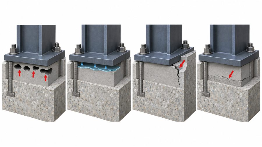
1. Voids and incomplete bearing
Air can become trapped under stiffeners, shims or low points when grout loses flow before it reaches the outlet. Feeding from several uncontrolled directions may create colliding flow fronts that enclose air. Leaking formwork can also reduce the placement head needed to drive grout through the gap.
An edge void does not reveal the complete internal geometry. Map the suspected area before choosing a repair.
2. A gap beneath the baseplate
Bleeding, settlement or volume loss can leave a thin separation at the steel interface. A sounding survey may indicate debonding, but sound is affected by plate thickness, ribs, anchors and support conditions. Confirm important findings with a second method.
3. Shoulder cracking
The exposed grout shoulder dries faster and experiences different restraint and temperature than the material under the plate. Wide or poorly detailed shoulders are especially vulnerable. A shoulder crack may be superficial, yet a crack that continues beneath the plate or shows differential movement demands further assessment.
4. Cold joints
An interruption can allow one lift to stiffen before placement resumes. The resulting interface may have low bond and can become a leakage or crack path. Construction records, grout color/texture and cores can help distinguish a cold joint from a later service crack.
Other Failure Patterns and Their Clues
| Observation | Plausible causes | Evidence needed before conclusion |
|---|---|---|
| Powdering or soft surface | Excess water, rain damage, early drying, contamination | Depth profile, strength samples, placement weather and batch records |
| Map cracking | Rapid moisture loss, thermal gradient, restraint, unsuitable water content | Crack depth, timing, temperature and curing history |
| Local crushing | High bearing stress, misalignment, inadequate strength or void-adjacent concentration | Load analysis, contact geometry, material strength |
| Rust staining | Water path, corroding steel, contaminated interface | Moisture source and steel condition |
| Oil-softened surface | Hydrocarbon exposure or contaminated substrate | Chemical identification and depth of damage |
| Recurrent bolt loosening | Vibration, alignment, preload or loss of support | Bolt-tension, vibration, alignment and bearing assessment |
| Hollow sounding | Debonding, void, geometry change or plate resonance | Calibrated survey plus confirmatory investigation |
Treat this table as a hypothesis generator. Several mechanisms can create the same symptom, and several defects can occur together.
A Step-by-Step Diagnostic Workflow
Step 1: Make the equipment safe
Before inspection, follow the site’s isolation, lockout and access procedures. Do not loosen anchors, drill near reinforcement or load-test operating equipment without authorization. If there is active movement, severe crushing or rapid alignment change, escalate immediately to the responsible engineer.
Step 2: Define the grout’s design function
Obtain foundation drawings, equipment loads, baseplate details, shim arrangement and bolt requirements. Determine whether the plate was intended for full grout bearing or whether permanent shims carry part of the load. Without this context, an “acceptable bearing percentage” can be misapplied.
ACI PRC-351.1-12, reapproved in 2024, describes grouting between foundations and machinery bases, including materials, qualification, design/detailing, placement and QA/QC. It is a report, not a contract specification; any selected recommendations must be rewritten into mandatory project requirements.
Step 3: Reconstruct the installation
Collect the product data sheet and lot numbers, batch water, mixer type, mixing time, grout temperature, ambient conditions, flow tests, strength results, placement direction, interruptions and curing. Check photographs for form leaks, standing water, multiple feed points or unfilled vents.
The most valuable record is often actual water per bag. Added water above the qualified amount can increase flow temporarily while reducing strength and stability.
Step 4: Map visible conditions
Create a grid tied to fixed equipment coordinates. Record crack location, length, width, orientation and whether it changes across operating cycles. Mark edge voids, damp areas, rust, deposits and crushed zones. Repeat photographs from the same viewpoint with a scale.
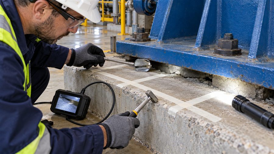
Step 5: Use investigation methods in increasing order of intrusion
| Method | What it can indicate | Important limitation |
|---|---|---|
| Visual survey | Surface distress, leakage and crack pattern | Cannot see internal bearing |
| Tapping/sounding | Changes in support response | Requires calibration; plate geometry affects sound |
| Borescope through approved access | Direct view of a local void or interface | Very local field of view |
| Survey/alignment monitoring | Movement or settlement over time | Does not identify material cause alone |
| Vibration and bolt-preload review | System response and anchorage behavior | Requires equipment expertise and baseline data |
| Ultrasonic or impact methods | Potential internal anomalies | Interpretation is geometry- and material-dependent |
| Core or drilled sample | Direct condition and laboratory testing | Intrusive; may hit anchors/rebar and alter load path |
No single method is universally conclusive. Combine independent evidence and involve the engineer of record, equipment supplier and grout manufacturer as appropriate.
Testing Grout Strength Without Misleading Comparisons
ASTM C109/C109M uses 50 mm cubes for hydraulic-cement mortar strength. Grout product data may use this or another permitted project method. Core strength from placed grout cannot be compared casually with molded cube results because specimen geometry, compaction, moisture, damage during extraction and slenderness differ.
Also distinguish:
- Laboratory-cured qualification specimens
- Field-cured samples exposed to site temperature
- Samples taken from the mixer discharge
- Hardened material removed from the actual base
If early release depended on a specified strength, verify that the accepted specimen and curing method represented the field condition required by the project.
Flow Evidence: Use the Right Method
ASTM C939/C939M-22 determines the efflux time of fluid grout through a standardized cone. Its scope applies to material with an efflux time of 35 seconds or less and fine aggregate passing a 2.36 mm sieve; when flow is slower, the standard directs users to a flow-table approach. A product’s flow value is meaningless unless the apparatus, timing, temperature and water content are known.
Flow is not an isolated acceptance goal. Grout that is made overly fluid with water may travel easily yet bleed or lose strength. The required property is complete, stable placement at the qualified water content.
Repair Decision Matrix
| Condition | Typical decision path | Engineering checks |
|---|---|---|
| Stable cosmetic shoulder crack | Seal, reshape or monitor if required | Crack depth, moisture path and whether crack enters bearing zone |
| Small confirmed edge void outside critical bearing | Engineered localized fill may be possible | Void extent, access, bond and injection pressure |
| Distributed voids beneath loaded plate | Partial or full regrouting often considered | Load transfer, safe unloading/support and achievable filling |
| Weak or segregated grout through depth | Removal and replacement may be necessary | Extent, cause, temporary support and anchor safety |
| Active movement or recurrent cracking | Correct system cause before grout repair | Alignment, vibration, anchors, foundation and operating loads |
| Chemical/thermal attack | Select compatible repair system after exposure control | Chemical identity, temperature and depth of deterioration |
Do not inject an unknown void simply because an opening is accessible. Injection pressure can lift or distort a plate, redistribute load, damage weak grout or block vents. The repair plan must define material viscosity, pressure limit, port sequence, venting, acceptance and equipment support.
Similarly, removing grout from beneath a loaded base can destabilize alignment or overload remaining contact points. Temporary support, removal limits and anchor treatment require an engineered sequence.
Root Causes and Prevention
Incorrect water measurement
Estimate water by mass or with a verified meter, not by an unmarked bucket. Include residual mixer water. Never retemper grout after it begins to lose flow unless an approved product procedure explicitly permits it.
Unsuitable mixing equipment
Low-speed drum mixing may leave lumps or fail to develop the intended rheology. Use the manufacturer-approved mixer, batch size and mixing time. Confirm that the pump and hose do not cause blockage or excessive delay.
Poor substrate preparation
Laitance, curing compound, oil and weak concrete reduce bond. Mechanically prepare to sound concrete and clean the steel contact surface as specified. For cementitious grout, bring concrete to the required moisture condition—often saturated surface-dry—without leaving standing water.
Form leakage and inadequate head
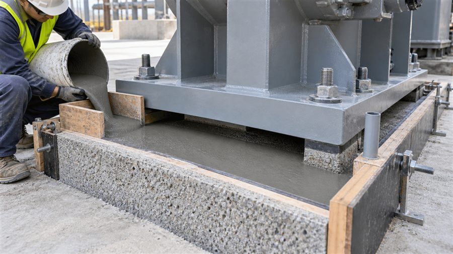
Fluid grout creates lateral pressure, while pumping can add more. Forms must be rigid, sealed and braced for the actual method. A one-sided head box or pump inlet should maintain a coherent advancing front toward controlled outlets and vents.
Interrupted placement
Calculate production rate from net grout volume and available working time. Provide enough material, water, labor, power and backup equipment to complete the pour continuously. A planned contingency is cheaper than improvising after the pump stops.
Poor curing and temperature control
Protect exposed cementitious grout immediately after finishing. Hot, dry or windy conditions accelerate water loss; cold conditions delay strength. Follow product limits for material, substrate and ambient temperature, and base release on verified strength—not elapsed time alone.
Shoulder geometry
Avoid unnecessarily wide or thick unrestrained shoulders. Detail the shoulder, chamfer or slope according to the project and product recommendations so water does not pond and stress concentration is limited.
Acceptance Checks Before Loading Equipment
Before releasing a base, confirm:
- Specified early strength has been achieved using the approved test and curing regime.
- Grout remained within qualified water, flow and temperature limits.
- Placement records show continuous filling and satisfactory discharge at vents/outlets.
- Required curing duration and temperature protection are complete.
- Forms have been removed only at the approved time and exposed grout inspected.
- Anchor tightening or tensioning follows the specified sequence.
- Alignment and elevation meet equipment tolerances.
- Any nonconformance has a documented engineering disposition.
Frequently Asked Questions
Are cracks in non-shrink grout always a failure?
No. Location, depth, movement and structural function matter. A stable surface crack in an exposed shoulder differs from a moving crack beneath the bearing area. Map and assess it before selecting repair.
Can hollow-sounding grout be repaired by epoxy injection?
Sometimes, but sounding alone does not define the void. The engineer should confirm extent, load condition, injection pressure, venting and compatibility. Uncontrolled injection can move the plate or leave isolated pockets.
Why did compliant grout shrink in service?
“Nonshrink” compliance is measured under standardized conditions. Excess field water, evaporation, dry substrate, leakage, temperature gradient, restraint or poor curing can still cause loss of contact or cracking.
Can extra water solve poor grout flow?
It may increase initial flow, but it can reduce strength, increase bleeding and alter volume stability. Use the qualified water range and correct mixing/placement equipment.
Should damaged grout be completely replaced?
Only after the defect extent and structural consequence are established. Localized stable defects may permit a targeted repair; distributed weak grout, active movement or widespread loss of bearing may require partial or full replacement under a designed support sequence.
Conclusion
Non-shrink grout failure should be diagnosed as a load-transfer problem, not judged from appearance alone. Define the grout’s function, reconstruct placement, map the condition and confirm critical findings with appropriate investigation. Then correct the root cause before repair. QD Material can assist with grout selection and method review, while decisions affecting support, anchors or equipment alignment must remain under the responsible engineer.
Technical References
- ASTM C1107/C1107M-20, Packaged Dry Hydraulic-Cement Grout (Nonshrink).
- ACI PRC-351.1-12, Report on Grouting Between Foundations and Bases for Support of Equipment and Machinery, reapproved 2024.
- ASTM C827/C827M-23, Change in Height at Early Ages of Cementitious Mixtures.
- ASTM C1090/C1090M-23, Height Change of Hydraulic-Cement Grout.
- ASTM C939/C939M-22, Flow of Grout by Flow Cone.
- ASTM C109/C109M, Compressive Strength of Hydraulic Cement Mortars.
Technical note: This article is a diagnostic framework, not authorization to unload, drill, inject or remove grout beneath equipment. Follow the site safety system and an engineer-approved investigation and repair plan.