
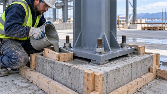
Base plate grouting creates the specified bearing interface between a steel column base plate and its concrete foundation. The work can look simple from outside the formwork, yet the critical contact surface is largely hidden. Material emerging from one opening does not automatically demonstrate complete support beneath the plate.
A useful installation plan connects the approved structural detail, grout properties, access, preparation, and inspection requirements. This article explains the decisions that contractors and engineers should resolve before a pour. It is a planning guide: the project drawings, current product instructions, and engineer-approved method govern the actual installation.
Understand the Base Detail Before Starting
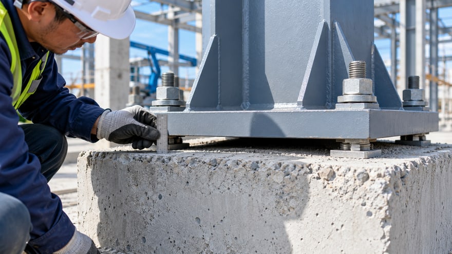
Review the function of the grout within the designed connection. Identify the plate footprint, gap, anchor arrangement, shear features, leveling system, and any pockets or vents. Confirm the intended construction sequence and the point at which the supported structure will receive load.
Do not change shims, leveling nuts, anchor details, or plate openings to make grouting easier without approval. These features may be part of the structural design or erection procedure. Record questions on the drawings and obtain answers before forms conceal the relevant surfaces.
Where the gap varies, record both the narrowest and deepest sections. A product suitable for the nominal gap may not suit a local pocket or obstruction. The approved material and procedure should cover the whole placement.
Base Plate Grouting Starts With a Feasible Flow Path
Plan where grout enters, how it travels, and where displaced air escapes. For a flowable placement, the arrangement should support a controlled advancing front rather than create opposing fronts that can trap air. Plate geometry and the chosen product determine the practical method.
Headboxes, feed arrangements, and venting should be resolved during planning. Do not drill new holes in a structural plate without designer approval. For a large or complicated base, a trial arrangement can help the team identify access and flow problems before the main work.
The Euclid cementitious grout application guide provides manufacturer guidance on placement planning and continuity. Use it as an example of the issues a method statement must address, then follow the requirements of the approved product.
Select Non Shrink Grout for Steel Columns
Specify the required performance and installation conditions together. Relevant items include strength at the planned loading age, permitted placement depth, consistency, working time, exposure, and curing. Confirm whether the proposed grout can travel through the actual gap using the available method.
Ask the supplier to identify the water addition associated with the submitted properties. If a proposal includes results for several consistencies, clearly mark the consistency approved for the project. The batch instruction used on site should match that submission.
For background on the broader selection process, see our non-shrink grouting material engineering guide. Do not substitute tile grout or an improvised cement mixture for an approved structural product.
Prepare the Concrete and Steel Interfaces
Inspect the exposed concrete for weak surface material, contamination, damaged areas, and conditions that could interfere with the specified interface. Use the preparation method and surface condition required by the project and selected product. Remove debris before the forms make cleaning difficult.
The required concrete moisture condition is product-specific. Where instructions require a saturated surface-dry substrate, the surface should not contain standing water that can dilute the grout. Arrange inspection early enough to correct the condition before mixing begins.
Check the underside of the plate where accessible. Resolve oil, loose contamination, or incompatible coatings through the approved procedure. Do not assume that a painted or oily surface is acceptable simply because the grout develops high compressive strength.
Build Forms That Support the Placement Method
Forms must maintain the approved geometry and contain the grout during placement. Check joints, corners, feed access, escape paths, and the effect of placement pressure. Protect anchor components and other areas that must remain free of grout.
Allow enough access to introduce material effectively. At the same time, avoid oversized exposed shoulders created only for convenience. The final shoulder profile and form removal sequence should follow the approved detail and product instructions.
Check that the team can observe the designated outlet or vent locations. Formwork that blocks the inspection points can make it difficult to judge progress or recognize a leak while the grout remains workable.
Organize Mixing and Delivery as One Operation
Prepare enough trained personnel, mixing capacity, measuring equipment, and material for the planned pour. Establish who measures water, who records batches, who places grout, and who watches the outlet and forms. Confirm a response plan for interruptions before starting.
Use the approved mixer, sequence, batch size, and mixing duration. Measure water rather than estimating it. Keep bags protected and reject material whose condition or identity cannot be confirmed.
Move mixed grout to the base without avoidable delay. If placement cannot continue within the permitted period, follow the approved interruption procedure. Do not retemper stiffening grout or combine old and fresh batches as an improvised recovery method.
Place, Protect, and Record
Follow the approved entry point and maintain the planned direction of flow. Observe designated escape points and watch for leakage, blocked flow, segregation, or an interruption in supply. Keep a record of unusual events so the inspection team can assess their significance.
Do not use a generic rule that every grout should be vibrated. Placement assistance, including rodding, strapping, pumping, or vibration, must be compatible with the selected product and approved method. An unsuitable technique can change how the material behaves beneath the plate.
Begin the specified curing and environmental protection when required by the product instructions. Prevent damage from adjacent work and preserve access for inspection. Record placement time, conditions, batches, samples, and the protection method used.
A Site Inspection Plan
| Stage | Inspection question | Record or action |
|---|---|---|
| Before preparation | Does the installed geometry match the approved detail? | Measured gaps and identified discrepancies |
| Before forming | Are interfaces prepared and accessible for inspection? | Preparation acceptance |
| Before mixing | Are product, water, equipment, and personnel ready? | Pre-pour release |
| During placement | Is flow following the approved path without uncontrolled loss? | Batch and placement log |
| After placement | Is the specified protection in place? | Curing and temperature records as required |
| Before loading | Have the release criteria been met? | Documented engineer-authorized release |
The inspection plan should identify hold points and the person permitted to release each one. This avoids a situation in which workers must decide structural acceptance while the next construction activity is already waiting.
Keep the signed inspection records with the material batch records and placement drawing. Mark the specific base or foundation covered by each record. This allows a later technical review to connect observations and test evidence to the correct installation.
Investigate Suspected Voids Before Repairing Them
A visible edge defect or an unusual sounding response may justify further assessment, but neither defines the full internal condition by itself. Agree on an investigation method with the engineer. Access, geometry, and the consequence of incomplete support affect the appropriate approach.
Do not conceal an uncertain installation by filling only the visible perimeter. A repair proposal should address the location and extent of the defect, access, material compatibility, and a method to verify the result. Keep the affected base within the agreed loading restrictions until it is accepted.
Quantity and Procurement Planning
Estimate the cavity from actual dimensions and include the approved feed arrangement, pockets, and other filled features. Convert the required volume into bags using the selected product’s mixed yield. Our grout quantity calculation guide explains the calculation approach.
Keep a suitable contingency for site conditions, but distinguish unused reserve stock from the volume expected inside the base. Confirm delivery timing and storage so that replacement stock is available without relying on a different, unapproved product during placement.
Frequently Asked Questions
What Is the Minimum Grout Thickness Under a Base Plate?
There is no single value suitable for every material and detail. Use the designer’s gap together with the selected product’s depth limits and placement requirements. Resolve any conflict before installation.
Can Grout Be Poured From Both Sides?
Use the approved method. Introducing opposing flow fronts can create air-entrapment concerns, so a change in feed arrangement requires review rather than a site assumption.
Does Grout at the Outlet Prove Complete Bearing?
It shows that material reached that outlet. Full acceptance depends on the approved procedure and inspection criteria, including any additional verification required for the detail.
When Can Forms Be Removed and the Column Loaded?
These are separate decisions. Follow product instructions for form removal and the engineer’s criteria for loading. Do not use elapsed time alone unless it is part of the accepted procedure.
Specify the Whole Installation
Reliable base plate grouting depends on preparation, flow, continuity, and curing as well as the selected material. Review the hidden contact area as a construction requirement from the beginning. A clear method statement and inspection plan make the work easier to execute and assess.
For a material inquiry to Hubei Qiandao New Materials Co., Ltd., supply the plate drawings, grout gap, flow path, installation conditions, required loading age, and quantity. Request a product-specific proposal and current application instructions before finalizing the purchase and installation schedule.